Objectively Optimizing My Scanner
I've been a long-time fan of analog photography. While shooting is fun, the digitization step has always been pretty tedious and unsatisfying. For 35mm, I bought a purpose-built scanner, the PrimeFilm XA Super. This is a pretty nice device, especially paired with VueScan. The scanner is unfortunately out of production now, but they can be had for not that much on eBay.
For medium and large format, however, things get tricky. There's quite a few different medium format formats, and large format is, well, large. Usually, people then resort to flatbed scanning as an "all in one" solution. I picked up an Epson v700 not too long ago from a dentist that was going out of business, but have been unsatisfied with the results (as people will often tell you).
The first quirk of this scanner, as I found out, is that the optimum focus is some arbitrary distance off the glass when scanning in transparency mode. There are a bunch of holders out there for 35mm to 8x10, but most of them are total junk. And if they are even adjustable, many have fixed positions - which is not quite correct as the focus isn't some discrete distance from the surface of the glass.
So, in an attempt to get the most out of my flatbed (as I really don't want to shell out $100 for a drum scan), I bought an adjustable dry mount from BetterScanning. These are nice because they have these set screws that allow you to fine tune the focus. Additionally, they hold film flat by either taping and squeezing the negatives against "anti-newton" glass, which stops some scanning artifacts.
How you find this focus, though, is frustratingly subjective. The official documentation says to keep turning by a quarter turn until the image "starts to get less sharp". This seems too close to the "better or worse" experience at the eye doctor. There's a better approach.
How to actually focus a scanner
As we are trying to maximize the sharpness of our scans, we can try to directly measure the "modulation transfer function" or MTF of the optical system. This function captures both the resolution and contrast capabilities of optics. This value of the MTF is a normalized dimensionless quantity versus spatial frequency. Basically, this function is a metric of how well the system can reproduce edges of increasing sharpness. As we're going to be performing an optimization, the shape of this curve isn't so important, but we can use the "MTF50" summary metric. This number is the spatial frequency that we can reproduce at 50% of the "power" of the DC (0 cycles/pixel) component. The higher this number, the sharper the overall system. I must also note here that there are other metrics we could you, due to the fact that how we interpret sharpness is a funky subject. Most literature, however, seems to indicate that MTF50 tracks well with perceived sharpness.
To measure this, we will use the "slanted edge" method. To do this, I used a flat shaving razor taped to the matte side of the ANR glass on the adjustable-height holder.

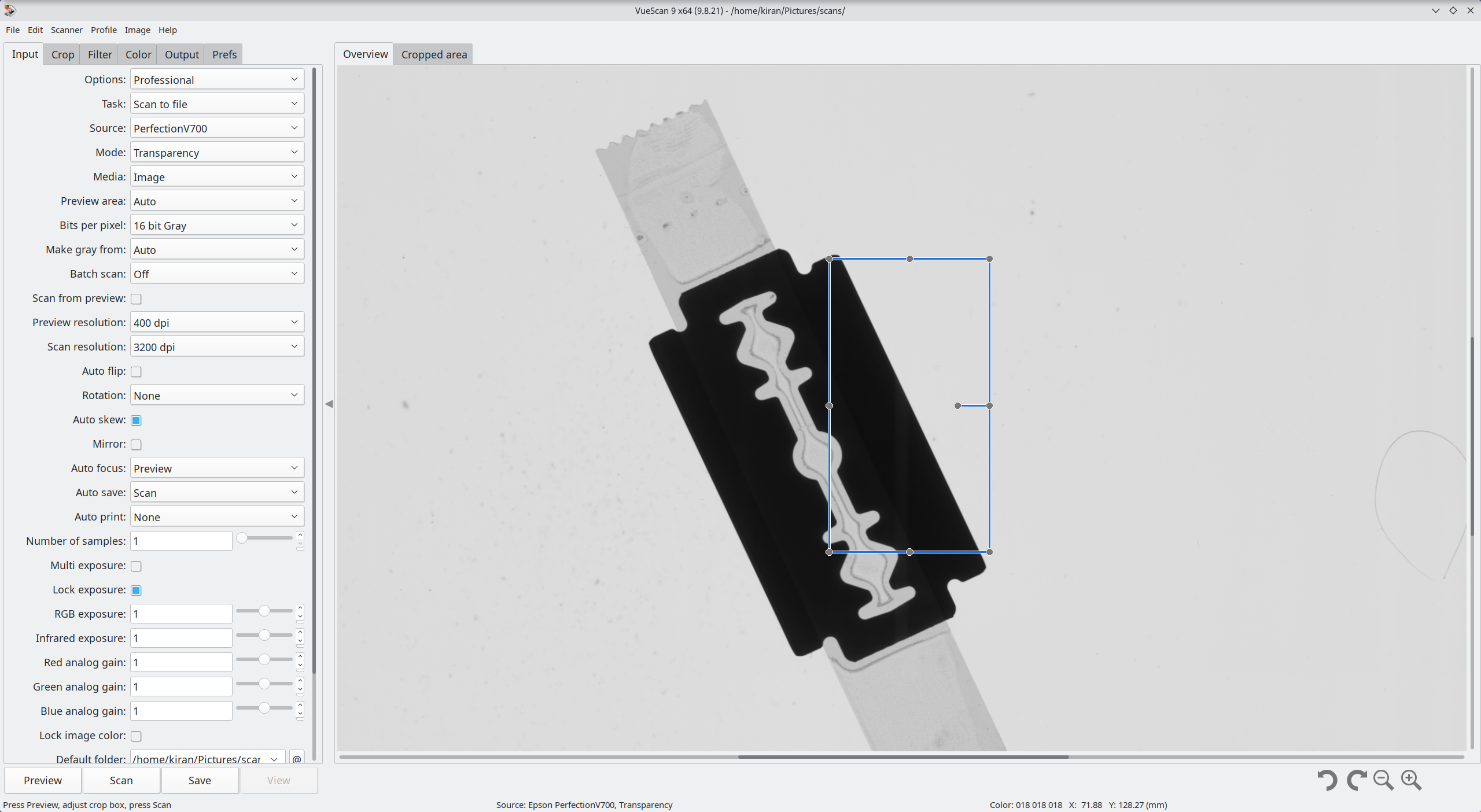
VueScan Settings
In VueScan, there are a few important things I needed to set:
- Transparency mode, so we're actually using the right lens pair for scanning film
- 16 bit grey mode, as slanted edge doesn't need color
- 3200 dpi, I won't need to scan more than this, and this is about the practical limit of this scanner
- Locked exposure, no color correction, no infrared cleaning, no sharpening to get the raw performance from just the scanner
Here is a screenshot of those settings
Procedure
So, the adjustable holder has eight set screws, all of which increase the height by 200 um when rotated a quarter turn. I zeroed them out and marked their position. Then, I took 15 measurements (scans of the razor's edge), each increasing the focus by 200um. As I measured the holder with calipers, the "zero" position was at 1.524 mm, so 15 quarter-turns puts us at a maximum of 4.124 mm, which should be past the focus.
After I have all these (labeled) TIF files, I move on to compute the MTF50 using a program called ImageJ. You'll also need the Slanted-Edge MTF plugin.
Using ImageJ, you open an image, go to plugins, and run SE MTF2xNyquist. You can either select a region to analyze or just let it use the whole image. I kept all the default options, and then generated the MTF. This will generate several plots, but we only need the one labeled MTF.
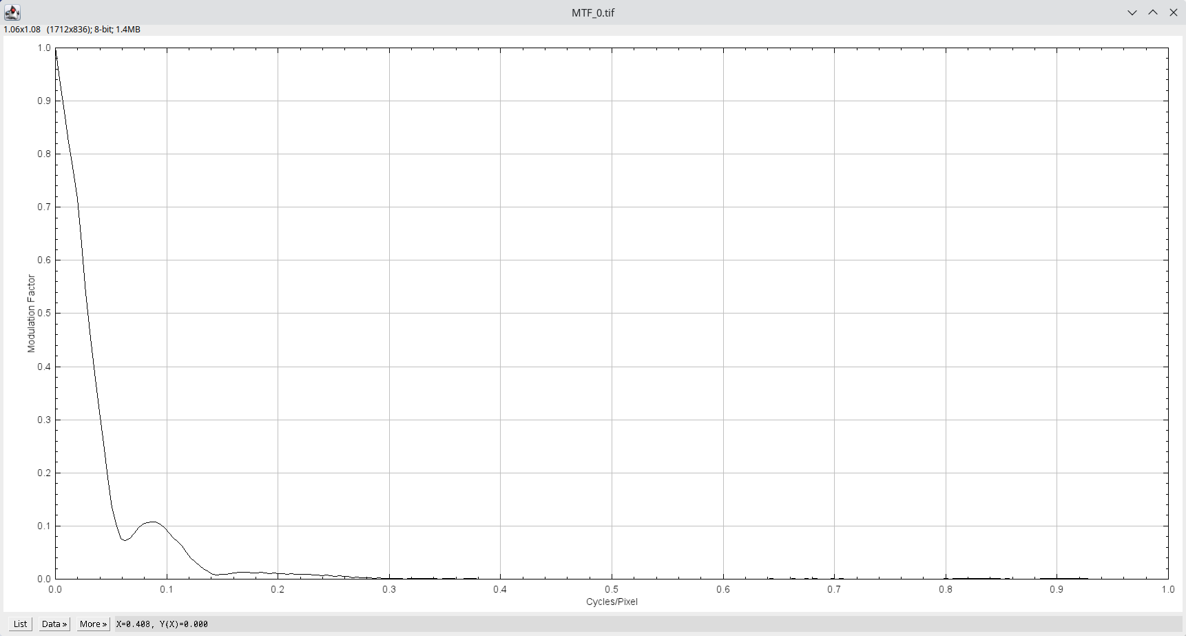
From there, I zoomed into the curve at the MTF = 0.5 point, and read off the x-value in cycles/pixel.
After doing this for every image I got the following measurements (including a zero point with no holder):
| Focus Height (mm) | MTF50 (c/p) |
|---|---|
| 0 | 0.0292 |
| 1.524 | 0.0497 |
| 1.724 | 0.0541 |
| 1.924 | 0.0566 |
| 2.124 | 0.0617 |
| 2.324 | 0.0677 |
| 2.524 | 0.0742 |
| 2.724 | 0.0816 |
| 2.924 | 0.0902 |
| 3.124 | 0.0934 |
| 3.324 | 0.0975 |
| 3.524 | 0.0979 |
| 3.724 | 0.0962 |
| 3.924 | 0.0932 |
| 4.124 | 0.0879 |
So, there's an obvious peak around 3.3-3.7.
Curve Fitting
Now, I want to interpolate these points to find the true maximum. I've seen people fit a parabola, but there's nothing about this system which implies a parabola. Additionally, there's error in both our focus height measurement and the MTF50 value. It makes more sense then to use a probabilistic approach. One such method is using a Gaussian process. This will optimize a mean and standard deviation function to our set of measurements.
I use the Julia programming language, which has an easy to use library for this. Here is the code snippet I used to fit the GP:
using CSV, Plots, GaussianProcesses, Optim
mtf = CSV.File("mtf50.csv", header = [:x, :mtf], skipto=2)
mz = MeanZero()
kern = SE(0.0, 0.0)
log_obs_noise = -1.0
gp = GP(mtf[:x], mtf[:mtf], mz, kern, log_obs_noise)
optimize!(gp; method=ConjugateGradient())
Here's a plot of the fit result:
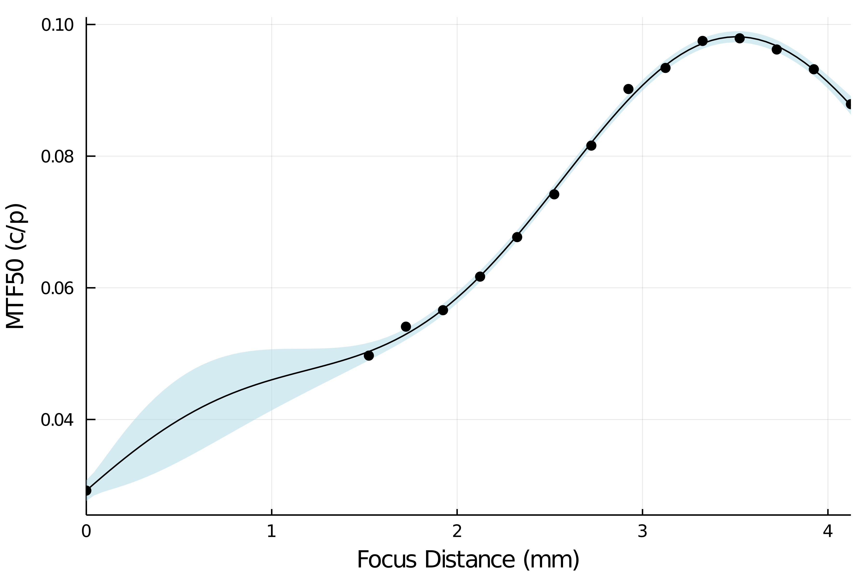
Then, I just took 100 points of the mean from 3 to 4 mm to find the maximum:
search = range(3, stop=4, length=100)
μ, _ = predict_y(gp, search)
_, i = findmax(μ)
focus_x = search[i]
Et viola! 3.5mm on the nose.
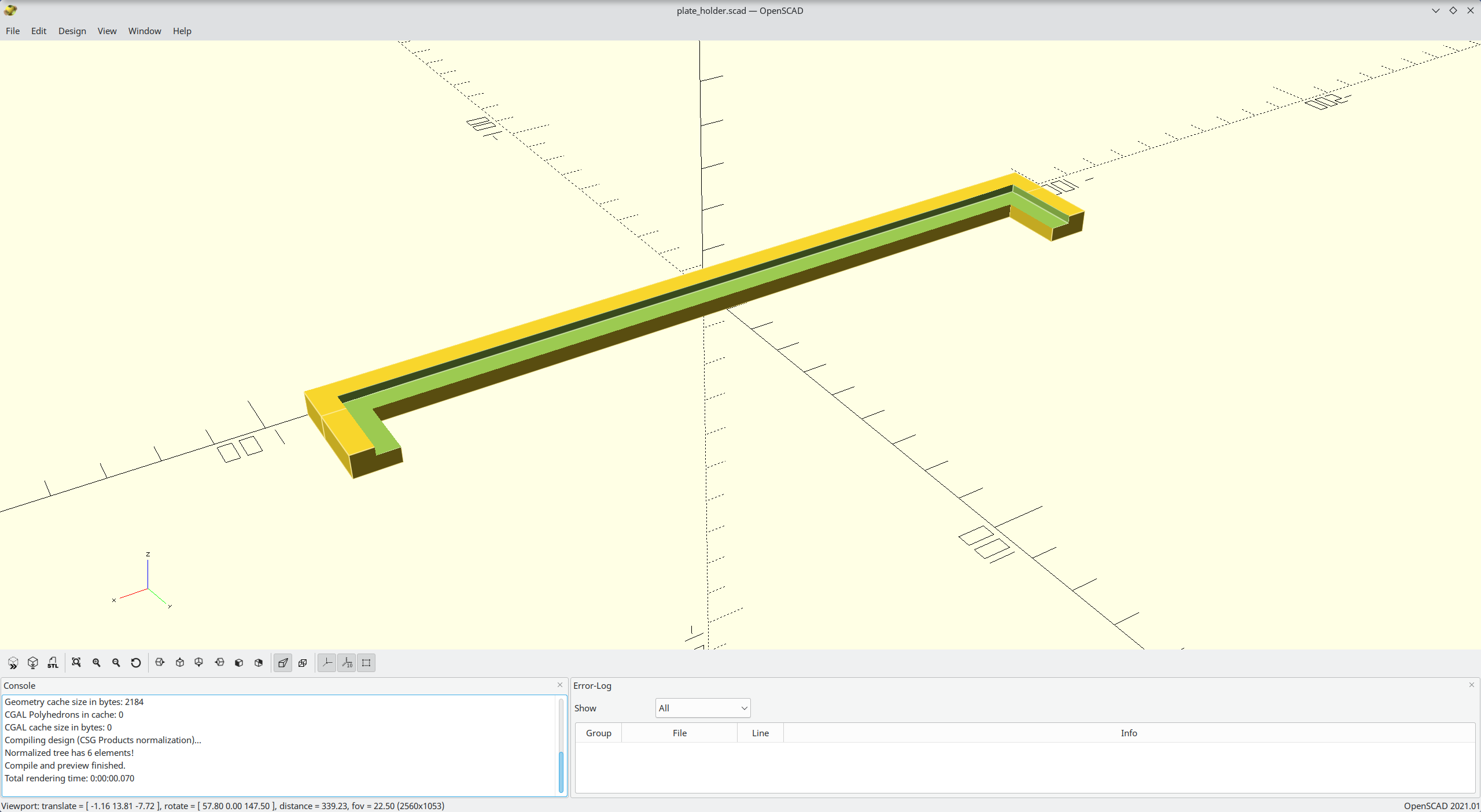
3D Printing a Bracket
Finally, I don't want to have to mess with the super fiddly adjustable bracket anymore, now that I know exactly the correct focus distance. So, I'll use my Prusa Mk3S 3D printer (which has good dimensional resolution) to print a holder for the glass that is exactly at 3.5mm above the scanner's bed.
I like to use OpenSCAD for this kind of thing, so I have something readily parametric. Here's the very simple design I came up with:
glass_width = 173;
glass_height = 2;
focus_height = 3.5;
holder_width = 10;
holder_edge = 25;

eps = 0.01;
total_height = focus_height + glass_height;

difference() {
  union() {
    translate([ -(glass_width + holder_width) / 2, 0, 0 ])
        cube([ glass_width + holder_width, holder_width, total_height ]);
    translate([ -(glass_width + holder_width) / 2, holder_width - eps, 0 ])
        cube([ holder_width, holder_edge - holder_width + eps, total_height ]);
    translate([
      (glass_width + holder_width) / 2 - holder_width, holder_width - eps, 0
    ]) cube([ holder_width, holder_edge - holder_width + eps, total_height ]);
  }
  translate([ -glass_width / 2, holder_width / 2, focus_height ]) cube([
    glass_width, holder_edge - holder_width / 2 + eps, glass_height + eps
  ]);
}
Rescanning the razor now, I get an MTF50 of 0.0983, which is above the maximum of all my measurements! Success!
Results
I've now scanned a bunch of my 4x5s with great success! I've had one picture drum scanned, and honestly it wasn't worth it. Sure, there was a little more detail, but you'd only notice it if you were blowing up the image to something ludicrous. Also, just adding a little bit of sharpening and "texture" in lightroom gives me almost the same results. So, I'm very happy with this and hope this might gives others a bit more confidence in their scanners for large-format work.