An Amaranth-Based Packetizer for the CASPER Toolflow
In the world of radio astronomy, the CASPER Collaboration is the go-to resource for tools supporting the design of digital electronics. They have open source hardware and software for radio astronomy instrumentation that greatly reduce the time to first science.
One of the core tools they provide is the "CASPER Toolflow". This is a collection of TCL and Python scripts that automate the generation of FPGA gateware using their library of MATLAB Simulink blocks. For tasks such as connecting a FIR filter block to an FFT block to perform a STFT (or polyphase filterbank (PFB), as radio astronomers like to call it), this is really plug and play. The blocks contains all the tricky functionality and it's up to the implementer to simply tie them together. While this is nice and simple for reuse of preexisting functionality, we quickly run into some downsides.
The problem
All of the downsides can be distilled into a single point, Simulink. As is true for all graphical langauges (LabView, etc.), programming ergonomics quickly drop off with design complexity. For example, if I want to design a state machine, I have to juggle registers, muxes, and so on - effectively re-implementing whatever would synthesize from some HDL's description of a state machine.
Second, there is no way to easily test a Simulink model. This may come as a shock, as the ability to simulate a model is kinda the selling point of the product. From my (albeit limited) experience, it's a total pain. One has to use gateway blocks to move in and out of the "hardware" domain, one has to remember that constants need to be sampled, etc. Once you get a result, there are multiple ways to display it, the default of which is the worst one. The "logic analyzer" is awful compared to that in Vivado or even the open source GTKWave. Finally, it's exceptionally slow. Simulink has to go through some horrendous type check process (which doesn't happen at connection time for some reason because it feel like they have some quadratic complexity in the type resolver (typical MATLAB)). Also, all of this suggests that every functional model will actually simulate, which I have found to not be the case. My simple model of an ADC block, filter, FFT, packetizer, and 10 GbE block just crashes if I hit simulate with incomprehensible errors. If one does manage to get a model to simulate, you can't run real unit tests against expected results. That is unless of course you have a license for the (for some reason) separate product Simulink Tests ($1.3k a year), which of course you can't run in CI.
Adding to all this, the Simulink-based toolflow requires two behemoth, expensive, proprietary tools - MATLAB (plus a collection of expensive add-ons) and Vivado. This implies you can't use a CASPER Simulink model on Intel (which has ~40% of the FPGA market share), Lattice, etc. FPGAs. Not only that, but all of the intrinsic connections to Xilinx IP implies you must use Vivado and not any of the open source backends, like those provided by F4PGA.
An analysis of the problem
The reason the CASPER Toolflow uses Simulink is so non-experts can quickly get working gateware. The graphical frontend is supposed to be simple enough that an astronomer can use the CASPER tutorials to throw together something working. I am not an astronomer, but am certainly a non-expert in digital electronics. I was not able to get something custom working without significant help (for which I am very grateful). The reasons for this were difficulty setting up the proprietary tools, understanding and implementing the glue logic between the provided functional blocks, and testing and interpreting what I have designed.
That last point being exceptionally important; I was not able to test my design without waiting for the 2 hour compile time, dealing with the hacky upload mechanics, and interpreting potentially missing UDP packets.
A solution
If I were to pick a computer technology that astronomers are familiar with, I would not have chosen a proprietary graph language, I would have said Python. Every astronomer and their mother uses Python. As such, it makes a bit more sense to try to leverage that experience.
To be fair, decent HDL tooling around Python is quite new and probably didn't exist when the CASPER folks decided to use Simulink. However, given the ecosystem of open source FPGA tooling and new "familiar" HDLs, it may be time to take the toolflow in a different direction. If a "high level connect the blocks together" style tool is still needed (which certainly may be the case), I think we should write our own in a way that is tailored to the usecase, and actually open source.
HDLs
There are several "alternative" HDLs out there, all of which seem like an improvement over the traditional VHDL/Verilog. CHISEL, BlueSpec, Lava, Clash all use a functional language (Scala/Haskell). These seem really cool and aligned well with the hardware-description concept, but there's no way an astronomer would learn Haskell just to write gateware. These packages are all intended for FP programmers who want to write FPGA code.
In the Python land, there's MyHDL, Migen, Amaranth, and a few others. MyHDL intends on transpiling python AST into hardware description (which comes with it's own bag of worms). The others (as far as I can tell) act as a lower-level interface to hardware. Of the options, I chose Amaranth for a few reasons:
It's tied in with Yosys and friends, the gold standard FOSS synthesis tool
- This includes the SymbiYosys formal verification tool
- It has a nice standard library of FIFOs, etc.
- It's not designed for HDL experts
- It can emit verilog that is supported by all the backends, including Vivado and Simulink + CASPER Toolflow
- The author, Catherine, knows what she's doing
There are a few downsides - mainly rough edges considering the tool is quite new. The documentation is lacking (but then, this is true for the CASPER tools). Also, there are a few quirks in the Verilog synthesis that need tweaking to get it to "just work" with Simulink.
A Packetizer in Amaranth
The rest of this post will focus on the design and implementation of a circuit to prepare packets for the CASPER 10 GbE block, a surprisingly tricky thing to design. The intention is to show that we could slowly incorporate Amaranth-based designs in the CASPER library, with the possibility of replacing the use of closed-source Simulink with Amaranth (or plain Verilog/VHDL) + F4PGA for an entirely open-source CASPER toolflow.
The task at hand
The 10 GbE yellow block in the CASPER Simulink library is one way to exfil high speed data to the outside world. To use it as an output, there are three critical connections:
- Data: Accepts 64 bit words every FPGA clock
- TX Valid: Indicates that the data presented on the
Datapin is valid and should be accepted into the internal FIFO - End of Frame (EOF): When high, this signal is coincident with the last word of valid data and starts the process of the core transmitting the packet.
The crux of the problem of connecting this to arbitrary data is forming the 64
bit words that we should present, along with the appropriate timing of the
tx_valid and eof signal. This is under the assumption that the data we want
to transmit is not already 64 bits.
In the case of the telescope I am designing (The Global Radio Explorer), the output of the PFB and requantization consists of parallel streams of requantized 8+8 bit complex data. These two streams are the channelized voltage data from the two polarizations of each antenna. In addition to each channel, I need to send a timestamp header such that the receiver knows how to order the packets (in case they arrive out of order) and their absolute UTC time. I can pack both polarizations into a 32 bit word, and collect two of those words every other clock cycle to form a 64 bit word suitable for the ethernet block.
To accomplish this, I'll fill up my own FIFO buffer (using the one provided in the standard library), and have state machines manage the loading and unloading.
To start, we need a few imports
from enum import Enum
from amaranth import *
In Amaranth, we can use enums as integers transparently, so we can have named states in our state machine. There are two different state machines in this design, one manages the timing signal, the other manages the FIFO.
Timing
In my design, I'll have an arm register that the user will set high in order
to start the timing process. When set high, the design waits for a PPS signal
from the GPS, which will align with an incoming ADC packet. The CASPER blocks
have synchronization inputs and outputs such that a pulse on the output is one
cycle before the first word of valid data. So, there are three states in the
packetizer:
- Waiting for an arm signal, which will halt any counters etc.
- Waiting for a sync signal, which will reset all the counters.
- Running
We can represent these states as:
class PacketizerState(Enum):
    WaitArm = 0
    WaitSync = 1
    Running = 2
The Design
In Amaranth, a synthesizable design subclasses the Amaranth Elaboratablable.
class Packetizer(Elaboratable):
    """The UDP packetizer for GReX Gateware."""
The constructor sets up all the inputs and outputs of a design and state, potentially parameterized.
In Amaranth Signal() is a single bit, Signal(n) is an unsigned n-bit
integer, Signal(signed(n)) is a signed n-bit integer, Signal(range(n)) will
have enough bits to represent n states, and Signal(n,reset=x)
will have an initial value of x.
To make a Simulink-compatible module, we must have clk (which will be implicit)
and a clock enable (called ce). We will use ce as a master enable.
To start, we will just try to follow these state transitions.
def __init__(self):
    ### Input Ports
    # Clock enable
    self.ce = Signal()
    # Timing Signals
    self.arm = Signal()
    self.sync_in = Signal()

    ### State
    self.state = Signal(PacketizerState, reset=PacketizerState.WaitArm)
In addition to a constructor, there must be an elaborate method that takes a
"platform" as it's second argument. In the case of this packetizer, I'm not
using any platform specific features, so I'll leave it blank.
We start by creating the module that will "contain" the design.
def elaborate(self, _) -> Module:
    # Instatiate the module
    m = Module()
To add a hardware connection in Amaranth, you have to add an assignment to the
appropriate "domain". There are two types of domains, combinatorial and
synchronous. By default, there are accessible under m.d.sync and m.d.comb,
respectively. Sync domains have "state", in that the assignment you describe
will occur on the next clock transition (rising edge by default) whereas comb
domain assignments occur instantly and fall back to their "reset" state when
they are not assigned.
To start our design, we must handle state transitions. Unfortunately, Python's flow control
statements aren't extensible, so we must describe choice with the If generator
method on the module itself. We will gate all of our logic begin a check to make
sure the clock enable (self.ce) is high.
In English, if we receive an arm pulse and we are in the WaitArm state, the
next state is the WaitSync state. If we are already running, return to the
WaitSync. If we are already in the WaitSync state, stay there. This
simplifies to stating that whenever we get an arm pulse, the next state is WaitSync.
# ...
with m.If(self.ce):
    with m.If(self.arm):
        m.d.sync += self.state.eq(PacketizerState.WaitSync)
Then, if we get a sync pulse and we are in the WaitSync state, the next state
is running.
# ...
    with m.If(self.sync_in):
        with m.If(self.state == PacketizerState.WaitSync):
            m.d.sync += self.state.eq(PacketizerState.Running)
The last thing the elaborate method must do is return a module (as indicated by the type signature).
# ...
return m
This is enough logic to start setting up the tests. First, we import the simulator:
from amaranth.sim import Simulator()Then we will start writing the function that can be tested by pytest. In
amaranth, you can yield assignment calls to describe the next clock
transition, yeild values to query the current value, and yield by itself to
advance the clock one cycle. One then adds the function that performs these
operations (a generator function) to the simulator with add_sync_process, you
add a clock signal with a time step, and then run. Here, we will run the
simulator with a waveform capture context so we can observe the output.
def test_packetizer():
    dut = Packetizer()
    sim = Simulator(dut)
    def process():
        # Setup some initial state
        yield dut.arm.eq(0)
        yield dut.sync_in.eq(0)
        yield dut.ce.eq(0)
        yield
        # Check the state
        assert (yield dut.state) == PacketizerState.WaitArm.value
        # Enable the clock and toggle arm
        yield dut.ce.eq(1)
        yield dut.arm.eq(1)
        yield
        yield dut.arm.eq(0)
        yield
        # Check the state
        assert (yield dut.state) == PacketizerState.WaitSync.value
        # Toggle the sync_in
        yield dut.sync_in.eq(1)
        yield
        yield dut.sync_in.eq(0)
        yield
        # Check the state
        assert (yield dut.state) == PacketizerState.Running.value
    sim.add_sync_process(process)
    sim.add_clock(1/250e6)
    with sim.write_vcd("waveform.vcd"):
        sim.run()
Running the test throws no errors and we can observe the output waveform.vcd
in GTKWave.
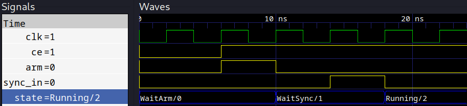
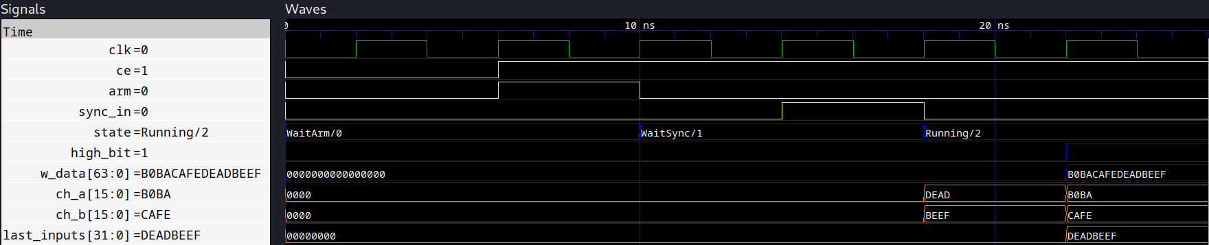
Perfect! Now we will start to add some functionality. The first thing we need to do is to collect two time samples of the parallel input data streams to create a 64 bit word. So, we need to define the two input ports, one for each polarization, a buffer to hold the last word, and a state bit to know whether we are on the high bit or low bit.
To more firmly describe, say at T=0 (Channel 0), POL_A = 0xDEAD and POL_B=0xBEEF. Then on T=1 (Channel 1), Pol_A = 0xB0BA and Pol_B=0xCAFE. On T=1, we will write the word 0xB0BACAFEDEADBEEF into the FIFO. This order will ensure all the channels are in the canonical, descending order.
So, we will add
INPUT_SIZE = 16
# Inputs
self.ch_a = Signal(INPUT_SIZE)
self.ch_b = Signal(INPUT_SIZE)
# State
self.high_bit = Signal()
self.last_inputs = Signal(2*INPUT_SIZE)
to the constructor. We will also add a temporary output signal to represent what we will write to the FIFO.
WORD_SIZE = 64
self.w_data = Signal(WORD_SIZE)
To start our logic, we will put the remainder of the stuff we will write under
with m.If(self.state == PacketizerState.Running):
    # ...
as we only want to do stuff if everything is running.
When we are on the first (self.high_bit = 0) clock, we will concatenate the two
inputs and store it in self.last_inputs. If we are on high bit
(self.high_bit = 1), we will concatenate self.last_inputs with the same
concatenation of the inputs and assign that to the test output signal. As we
have statefullness here, we must use the sync domain.
Amaranth gives us the Cat method to add bits together, least significant word first.
# ...
packed_inputs = Cat(self.ch_b, self.ch_a)
with m.If(~self.high_bit):
    m.d.sync += self.last_inputs.eq(packed_inputs)
    m.d.sync += self.high_bit.eq(~self.high_bit)
with m.Else():
    m.d.comb += self.w_data.eq(Cat(self.last_inputs,packed_inputs))
    m.d.sync += self.high_bit.eq(~self.high_bit)
Then we can add some tests to our process function:
# ...
# Toggle the sync_in
yield dut.sync_in.eq(1)
yield
yield dut.sync_in.eq(0)
# Set our test values (As this is one cycle after the sync)
yield dut.ch_a.eq(0xDEAD)
yield dut.ch_b.eq(0xBEEF)
yield
# Check the state
assert (yield dut.state) == PacketizerState.Running.value
# Set the next words
yield dut.ch_a.eq(0xB0BA)
yield dut.ch_b.eq(0xCAFE)
yield
# Check the output
assert (yield dut.w_data) == 0xB0BA_CAFE_DEAD_BEEF
This passes and the waveforms look correct!
Now we can attach this to a FIFO. We will use the synchronous, buffered FIFO documented here. To use it, we have to import it:
from amaranth.lib.fifo import SyncFIFOBufferedand then instantiate it as a "submodule" to the module we are constructing in
the elaborate method. It is at this point that we need to consider how many
words constitute an entire payload as this will set the FIFO depth. We can pass
this in as a parameter to the constructor
def __init__(self, n_words:int):
    # ...
    self.n_words = n_words

def elaborate(self) -> Module:
    # ...
    # 1 header word + 2 cycle delay before we start draining
    m.submodules.fifo = fifo = SyncFIFOBuffered(width=WORD_SIZE, depth=self.n_words+3)
    # ...
We want to delete the w_data signal now, because it exists in the FIFO. To
load data into the FIFO, we assign data to w_data and set w_en high.
We also now want to consider the header, which will simply be a 64 bit counter
of the number of payloads we've sent. Because we know the cadence of packets
from the FPGA clock and the number of channels, and we know the timestamp of the
first sample because that's this next second after we set arm high, we can
work out the explicit timestamp of each payload.
To do this, we need to create a counter for the number of payloads we've sent and a counter for the words we've shifted into the current FIFO.
In the constructor:
# ...
self.words = Signal(range(n_words+1)) # One extra word for the header
self.payloads = Signal(WORD_SIZE)
We have an edge case on the initial transition from WaitSync to Running in
that we need to shift in a word of zeros as the first header.
# ...
with m.If(self.sync_in):
    with m.If(self.state == PacketizerState.WaitSync):
        m.d.sync += self.state.eq(PacketizerState.Running)
        m.d.comb += fifo.w_data.eq(self.payloads)
        m.d.comb += fifo.w_en.eq(1)
Then, instead of writing to our own w_data, we use the FIFO's and increment
the counter. When we are constructing the low half (not pushing into the FIFO)
and we've already written all the words we wanted, we need to clear the word
counter and push a new header for the upcoming payload.
# ...
with m.If(self.state == PacketizerState.Running):
    packed_inputs = Cat(self.ch_b, self.ch_a)
    with m.If(~self.high_bit):
        m.d.sync += self.last_inputs.eq(packed_inputs)
        m.d.sync += self.high_bit.eq(~self.high_bit)
        with m.If(self.words == self.n_words):
            # Reset the counters
            m.d.sync += self.words.eq(0)
            # Increment the payload counter
            new_payload = self.payloads + 1
            m.d.sync += self.payloads(new_payload)
            # Push the new header
            m.d.comb += fifo.w_data.eq(new_payload)
            m.d.comb += fifo.w_en.eq(1)
    with m.Else():
        # Push the word
        m.d.comb += fifo.w_data.eq(Cat(self.last_inputs,packed_inputs))
        m.d.comb += fifo.w_en.eq(1)
        # Increment the word counter
        m.d.sync += self.words.eq(self.words + 1)
        # Update the state
        m.d.sync += self.high_bit.eq(~self.high_bit)
We can now update the tests to use a small word count (say 4) and remove the last test, just so we can observe the waveforms. Specifically, we can check that the cycle after we write a words sets our word counter to one
# ...
# Set the next words
yield dut.ch_a.eq(0xB0BA)
yield dut.ch_b.eq(0xCAFE)
yield
yield
# Check the output
assert (yield dut.words) == 1
You'll note in these waveforms that w_en is high when it's supposed to, loading the header of 0 and the first word we constructed. Now, we will use a for loop to generate some data to see the whole cycle for a complete payload.
# ...
def process():
    yield dut.arm.eq(0)
    yield dut.sync_in.eq(0)
    yield dut.ce.eq(0)
    yield
    # Check the state
    assert (yield dut.state) == PacketizerState.WaitArm.value
    # Enable the clock and toggle arm
    yield dut.ce.eq(1)
    yield dut.arm.eq(1)
    yield
    yield dut.arm.eq(0)
    yield
    # Check the state
    assert (yield dut.state) == PacketizerState.WaitSync.value
    # Toggle the sync_in
    yield dut.sync_in.eq(1)
    yield
    yield dut.sync_in.eq(0)
    for i in range(0,32,2):
        # Set our test values
        yield dut.ch_a.eq(i)
        yield dut.ch_b.eq(i + 1)
        yield
    yield
    yield
    # We've written 8 words, now the payload counter should be 2
    # Implying the last cycle we wrote a header payload of 2
    assert (yield dut.payloads) == 1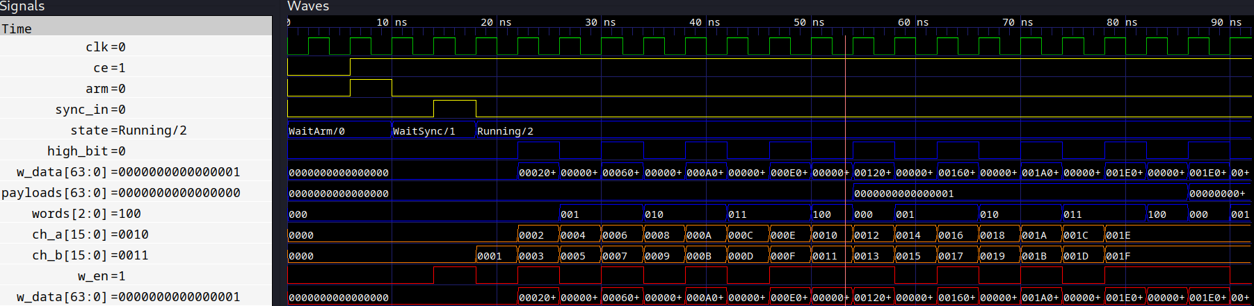
All of this looks correct, after we have written 8 words and a header, we write the new payload count of 2. We can also see that after the first four words, the header gets pushed, the next header of payload=1 gets pushed, and then the next two ADC words (channel 0) get push.
Now we can move on to the outgoing data that is intended for the 10 GbE yellow
block. We have three output lines, tx_data, tx_valid, and tx_eof. We can
setup a separate state machine to handle these signals that will run
simultaneously to all the loading logic. There are three states:
Loading: indicating thattx_validis falseDraining: indicating thattx_validis trueEOF: indicating this is the last cycle for whichtx_validis true
In the same file, we can setup the state enum:
class FIFOState(Enum):
    Loading = 0
    Draining = 1
    EOF = 2
Create the output ports in the constructor, as well as a state variable for the FIFO state and a counter to keep track of how many words we've drained:
def __init__(self, n_words:int):
    # ...
    self.tx_data = Signal(WORD_SIZE)
    self.tx_valid = Signal()
    self.tx_eof = Signal()
    self.fifo_state = Signal(FIFOState,reset=FIFOState.Loading)
    self.drain_count = Signal(range(n_words+1))
At the same level as the check to make sure the packetizer state is Running,
we can declare our state transitions.
If we are Draining, we enable the FIFO output by setting r_en to high, we
set tx_valid high (buffered by using m.d.sync), set tx_data to the fifo
data, update how many words we've drained, and check to see if we're one away
from the last word, indicating EOF - in which case we'd transition to EOF. If
we're in EOF, the next clock will be Loading, in which case we assign the
output signals to the final word.
with m.If(self.fifo_state == FIFOState.Draining):
    # Connect the outputs
    m.d.sync += fifo.r_en.eq(1)
    m.d.sync += self.tx_valid.eq(1)
    m.d.sync += self.tx_data.eq(fifo.r_data)
    # Start counting how many words we've drained
    m.d.sync += self.fifo_drain_count.eq(self.fifo_drain_count + 1)
    # We need to drain exactly n_words + 1 (for the header)
    with m.If(self.fifo_drain_count == self.n_words - 1):
        m.d.sync += self.fifo_state.eq(FIFOState.EOF)
with m.Elif(self.fifo_state == FIFOState.EOF):
    # Last words
    m.d.sync += fifo.r_en.eq(0)
    m.d.sync += self.tx_valid.eq(1)
    m.d.sync += self.tx_eof.eq(1)
    m.d.sync += self.tx_data.eq(fifo.r_data)
    # Reset the counter
    m.d.sync += self.fifo_drain_count.eq(0)
    # Back to just loading
    m.d.sync += self.fifo_state.eq(FIFOState.Loading)
with m.Else():
    m.d.sync += self.tx_eof.eq(0)
    m.d.sync += self.tx_valid.eq(0)
    m.d.sync += self.tx_data.eq(0)
The last step is then to enter the draining state when we've completed filling the FIFO, which is in the same place that we push the next header word.
# ...
# Push the new header
m.d.comb += fifo.w_data.eq(new_payload)
m.d.comb += fifo.w_en.eq(1)
# Start draining
m.d.sync += self.fifo_state.eq(FIFOState.Draining)
m.d.sync += fifo.r_en.eq(1)
We'll now restructure the tests a little bit, to write a bunch of words, and then check that the second payload is what we expect. We want a kinda proof-by-induction case here.
Amaranth does support the SymbiYosys formal verification backend, but this post is long enough.
Here is the new complete process function with some inline explanation:
def process():
    yield dut.arm.eq(0)
    yield dut.sync_in.eq(0)
    yield dut.ce.eq(0)
    yield
    # Check the state
    assert (yield dut.state) == PacketizerState.WaitArm.value
    # Enable the clock and toggle arm
    yield dut.ce.eq(1)
    yield dut.arm.eq(1)
    yield
    yield dut.arm.eq(0)
    yield
    # Check the state
    assert (yield dut.state) == PacketizerState.WaitSync.value
    # Toggle the sync_in
    yield dut.sync_in.eq(1)
    yield
    yield dut.sync_in.eq(0)
    # Write some words
    for i in range(0, 8 * n_words, 4):
        # Set our test values
        yield dut.ch_a.eq(i)
        yield dut.ch_b.eq(i + 1)
        yield
        yield dut.ch_a.eq(i + 2)
        yield dut.ch_b.eq(i + 3)
        yield
    yield  # One cycle to latch the last word
    yield  # One cycle to enter the drain state
    yield  # One cycle for it to propogate to the output
    # Then check the output
    # First is the header (1, we skipped testing the first one)
    assert (yield dut.tx_valid)
    assert (yield dut.tx_data) == 1
    yield
    for i in range(4 * n_words, 8 * n_words, 4):
        # Test our last values
        value = (i + 2) << 48 | (i + 3) << 32 | (i) << 16 | (i + 1)
        assert (yield dut.tx_data) == value
        assert (yield dut.tx_valid)
        yield
These tests all pass, and here are the waveforms, removing some unnecessary ones.
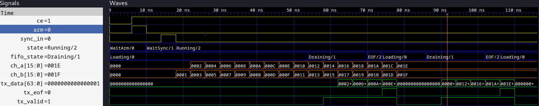
The final step before we can move over to Simulink is to ensure this works for
our true n_words of 1024 (which is half the number of channels). We can simply
rerun the same tests, but with this limit.

Which of course it works fine. Imagine doing this in Simulink, this took 1.5s to simulate on my laptop.
Combining the design with Simulink
If we didn't need Simulink at all, Amaranth is directly synthesizable to RTL using Yosys, but that isn't the case here because we need the rest of the CASPER tools (for now). As such, we will have to export the design as Verilog and import it as a black box in Simulink.
Exporting as verilog is easy enough, there is a single Amaranth function that
does this. We will hand it the device under test we just created (with n_words
= 1024), and explicitly list the inputs and output ports.
p = Packetizer(1024)
with open("packetizer.v", "w") as f:
    f.write(
        verilog.convert(
            p,
            ports=[
                p.ch_a,
                p.ch_b,
                p.sync_in,
                p.arm,
                p.ce,
                p.tx_data,
                p.tx_valid,
                p.tx_eof,
            ],
            name="packetizer",
            strip_internal_attrs=True,
        )
    )
The first gotchya here is that no external ports can be named input, output,
or inout. While Amaranth does the correct job in escaping these (as in, it
creates perfectly valid Verilog), whatever verilog parser Simulink is using
apparently isn't spec-compliant and crashes. This is fine in our case.
The next gotchya is that simulink expects each verilog module to be in its own file. Again, this is not required by the standard - but is a limitation of the Simulink Verilog parser, complain to them to fix their product.
To automate this step, we will use the (I'm so sorry) perl library Verilog::EditFiles. Once you install this, you can write a quick script like
use Verilog::EditFiles;
my $split = Verilog::EditFiles->new(outdir => "simulink");
$split->read_and_split(glob("packetizer.v"));
$split->write_files();
to dump all the modules to their own file under a simulink directory. Once you
run this, you should get fifo.v, unbuffered.v (a submodule of the fifo lib),
and our main circuit packetizer.v.
Using the design from Simulink
Once we have these verilog files, we need to create a "black box" block in Simulink to contain them. Most of this is automated, with a few extra steps.
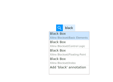
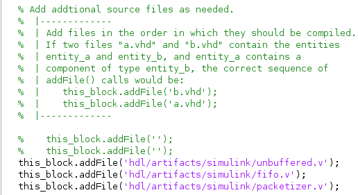
Because we split up the files, we have to include the "library" components in the MATLAB shim file it generated.
But after that, the generated block is good to go! Boolean outputs need cast
blocks for some reason, but other than that, they are plug and play.

Wrapping Up
Once this design went through the 2 hour Simulink churn, it worked the first try. That's the power of test-driven development and tools with a tight feedback loop. Next, I'm working on learning about formal verification to get even more confidence in the design as well as reimplimenting more of my questionable blocks.
I hope more CASPERites pick up Amaranth and maybe we can work together to form a nice standard library and board definitions for the CASPER products.
If you would like to see more on how I'm incorporating Amaranth in a radio telescope gateware, check out the project's repository here.
Thanks for reading!